


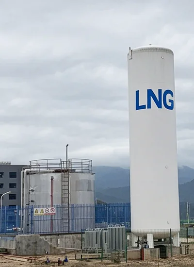
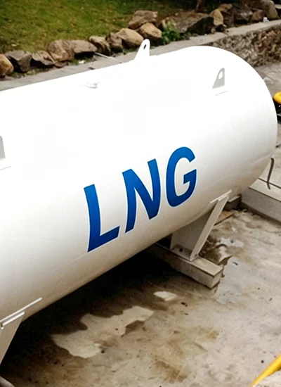
Inspection of cryogenic pressure vessels is a systematic engineering process used to evaluate storage systems designed for liquefied gases at extremely low temperatures. These systems typically store nitrogen, oxygen, argon, LNG, and other refrigerated gases under vacuum-insulated and high-pressure conditions.
The primary objective of inspection is to ensure structural integrity, vacuum performance, operational safety, and full regulatory compliance across the equipment lifecycle.
Regular inspection helps prevent:
- Gas leakage and product loss through boil-off
- Vacuum insulation failure
- Pressure system malfunction
- Catastrophic vessel rupture
- Regulatory non-compliance
These inspections are critical in industrial gas, medical oxygen supply, energy systems, and laboratory applications, where operational safety and gas purity are essential.
Scope of Inspection
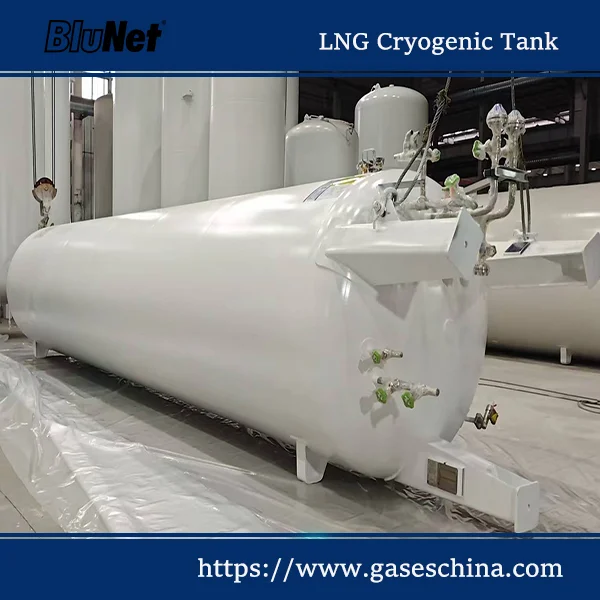
This article focuses on the inspection of static vacuum-insulated cryogenic pressure vessels used for storing refrigerated liquefied gases such as nitrogen, oxygen, and argon.
Included:
-
-
- Stationary cryogenic storage tanks
- Vacuum-insulated pressure vessels
- On-site industrial gas storage systems
-
Excluded:
-
- Transportable cryogenic tanks (ADR / TPED regulated)
- Gas production or liquefaction systems
- Mobile ISO tank containers
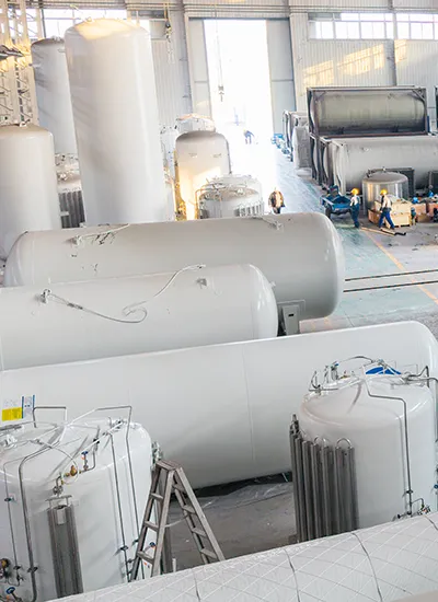
Types of Cryogenic Vessels Subject to Inspection
- Vacuum-Insulated Storage Tanks – primary industrial storage systems
- Cryogenic Vaporizers – convert liquid gas to gaseous form
- Low-Temperature Pressure Vessels – auxiliary process equipment
Inspection Standards and Regulations
Cryogenic pressure vessel inspection is governed by internationally recognized codes and regional enforcement systems.
Global Standards
ASME Boiler and Pressure Vessel Code (BPVC Section VIII, 2025 Edition)
- Primary global standard for pressure vessel design and inspection
- Introduces enhanced risk-based inspection (RBI) integration
- Requires advanced NDT verification for critical components
Pressure Equipment Directive (PED 2014/68/EU)
- Mandatory compliance framework in the European Union
- Defines essential safety requirements and conformity assessment
Regional Enforcement Authorities
- United States: OSHA + API 510 + ASME BPVC
- United Kingdom: Pressure Systems Safety Regulations (PSSR 2000)
- Germany: BetrSichV + TÜV inspection regime
- France: ESP (Équipements Sous Pression)
- Italy: INAIL certification system
- Switzerland: Pressure Equipment Ordinance
Risk-Based Inspection (RBI) Approach
Modern inspection strategies are shifting from fixed intervals to risk-based inspection planning, which evaluates:
- Probability of Failure (PoF)
- Consequence of Failure (CoF)
- Operating pressure and temperature cycles
- Service environment severity
This ensures inspection frequency is optimized based on actual operational risk rather than static schedules.
Inspection Methods and Procedures
Visual Inspection
- External shell corrosion, dents, and deformation
- Frost formation indicating insulation failure
- Valve, pipeline, and joint leakage detection
Pressure Testing
- Hydrostatic or pneumatic testing under controlled conditions
- Verification of maximum allowable working pressure (MAWP)
- Safety relief valve performance validation
Vacuum Integrity Testing
Vacuum performance is critical for cryogenic efficiency.
- Vacuum level typically maintained at 10⁻³ to 10⁻⁵ mbar
- Detection of vacuum insulation degradation
- Boil-off rate analysis as indirect performance indicator
Non-Destructive Testing (NDT)
- Ultrasonic Testing (UT) – wall thickness measurement (ASME Section V)
- Radiographic Testing (RT) – internal weld defect detection
- Helium Mass Spectrometry – high-sensitivity leak detection
- Dye penetrant testing for surface crack detection
Pressure Relief Device (PRD) Inspection
- Set pressure verification
- Reseating performance testing
- Redundancy check for dual-valve systems
Cryogenic Tank Inspection Workflow
Cryogenic tank inspection typically follows a structured engineering workflow to ensure safety, vacuum integrity, pressure performance, and regulatory compliance throughout the inspection process.
- Preparation and Isolation – Depressurize, isolate, and secure the cryogenic vessel before inspection.
- External Visual Inspection – Examine the outer shell, insulation jacket, supports, piping, and valves for corrosion, frost formation, dents, or leakage.
- Vacuum Integrity Evaluation – Verify vacuum performance through pressure measurements, boil-off analysis, or helium leak detection testing.
- Pressure System Testing – Inspect safety relief devices, pressure regulators, and piping systems under controlled conditions.
- Non-Destructive Testing (NDT) – Perform ultrasonic testing (UT), radiographic testing (RT), or dye penetrant testing to identify cracks or material degradation.
- Instrumentation Verification – Calibrate pressure gauges, level indicators, temperature sensors, and monitoring systems.
- Documentation and Compliance Review – Record inspection findings and verify compliance with ASME, PED, API 510, or local regulations.
A systematic workflow helps reduce operational risk, prevent vacuum failure, and improve long-term cryogenic storage reliability.
Cryogenic Vessel Inspection Checklist
- External shell condition and insulation jacket
- Vacuum pressure stability
- Relief valve certification and function
- Piping and valve leak tightness
- Instrument calibration (pressure, level, temperature)
- Structural weld integrity
- Boil-off rate consistency
Inspection Frequency and Intervals
Inspection intervals depend on operating conditions, regulatory requirements, and equipment design:
- Routine visual inspection: annually
- Comprehensive inspection: every 3–5 years
- Additional inspections after abnormal events or repairs
High cycling conditions or harsh environments may require more frequent inspections.
Cryogenic Vessel Inspection by Country (Regulatory Overview)
The inspection of cryogenic pressure vessels is not governed by uniform fixed intervals in most countries. Instead, each region applies a combination of international pressure vessel codes and national enforcement systems. The table below summarizes the regulatory framework and typical inspection approach.
| Country | Regulatory Framework | Inspection Approach | Key Standard / Code |
|---|---|---|---|
| Austria | EU PED Enforcement | Risk-based periodic inspection by authorized bodies | EN 13458 / PED 2014/68/EU |
| Belgium | EU PED + National Authority | Scheduled external inspection + safety valve testing | EN Standards + PED |
| Denmark | EU PED Framework | Periodic inspection based on risk classification | Danish Working Environment Authority + PED |
| Finland | EU PED + National Safety Act | Defined inspection intervals based on vessel category | Tukes Regulations + EN 13458 |
| France | EU PED + French Pressure Equipment Order | Mandatory periodic inspection by accredited bodies | ESP (Equipements sous pression) |
| Germany | BetrSichV + PED | Risk-based inspection by TÜV or notified bodies | TRBS / AD 2000 Code |
| Italy | EU PED + INAIL Authority | Scheduled inspection + safety device verification | INAIL Regulations + PED |
| Netherlands | EU PED + Labor Authority | Inspection intervals based on risk assessment | ARBObesluit + PED |
| Spain | EU PED + Industry Ministry | Periodic inspection + leak testing requirements | RIP (Reglamento de equipos a presión) |
| Sweden | EU PED + Work Environment Authority | Risk-based inspection regime | AFS Regulations |
| Switzerland | National Pressure Equipment Law | External inspections + periodic safety checks | Swiss Pressure Equipment Ordinance |
| United Kingdom | PSSR 2000 | Written Scheme of Examination (WSE) required | Pressure Systems Safety Regulations 2000 |
| United States | OSHA + ASME + API | Risk-based inspection (API 510) + ASME compliance | ASME BPVC Section VIII / API 510 |
Note: Inspection intervals are not fixed at the national level in most countries. Actual schedules depend on risk assessment, vessel design, operating conditions, and classification under applicable pressure equipment codes.
Common Defects and Failure Risks
- Loss of vacuum insulation
- Corrosion or material degradation
- Valve and seal leakage
- Structural fatigue from pressure cycling
- Micro-cracks in welds or vessel walls
Early detection of these issues significantly reduces operational risk and maintenance costs.
Vacuum Failure Symptoms in Cryogenic Tanks
Vacuum insulation failure is one of the most serious issues affecting cryogenic storage tanks and vacuum-insulated pressure vessels. Early detection is critical to prevent excessive boil-off gas losses, pressure instability, and operational hazards.
- Abnormal frost or ice formation on the outer vessel surface
- Increased boil-off gas (BOG) generation
- Rapid pressure rise inside the storage tank
- Higher product evaporation losses
- Reduced holding time for liquefied gases
- Condensation around piping connections or vacuum jacket areas
- Unexpected activation of pressure relief devices (PRDs)
Common causes of vacuum failure include insulation degradation, seal leakage, thermal cycling stress, mechanical damage, and deterioration of the vacuum jacket system.
Safety Considerations During Inspection
- Oxygen deficiency risk: Ensure proper ventilation
- Cryogenic burns: Use protective equipment
- Pressure hazards: Depressurize systems before testing
- Cold embrittlement: Avoid mechanical impact at low temperatures
Why Regular Inspection Is Critical
- Maintains structural integrity under extreme conditions
- Ensures insulation efficiency and reduces boil-off loss
- Prevents catastrophic failures and safety incidents
- Ensures compliance with regulatory requirements
Vacuum Failure Symptoms in Cryogenic Tanks
Vacuum insulation failure is one of the most serious issues affecting cryogenic storage tanks and vacuum-insulated pressure vessels. Early detection is critical to prevent excessive boil-off gas losses, pressure instability, and operational hazards.
- Abnormal frost or ice formation on the outer vessel surface
- Increased boil-off gas (BOG) generation
- Rapid pressure rise inside the storage tank
- Higher product evaporation losses
- Reduced holding time for liquefied gases
- Condensation around piping connections or vacuum jacket areas
- Unexpected activation of pressure relief devices (PRDs)
Common causes of vacuum failure include insulation degradation, seal leakage, thermal cycling stress, mechanical damage, and deterioration of the vacuum jacket system.
No comment