

Designing Cryogenic Storage Vessels
The design of cryogenic storage vessels involves careful calculation of several key variables, including vessel dimensions, insulation performance, material selection, and structural integrity.
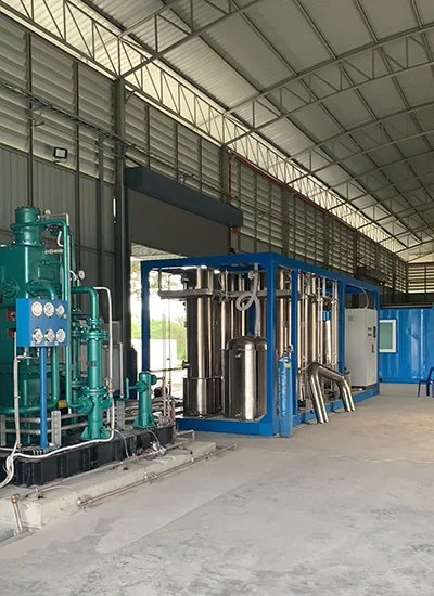
Before liquefaction, the incoming air is passed through a post-filter to remove impurities. The filtered air then enters the cold box, which consists of:
- Heat exchangers
- Expansion turbines
- Inlet and outlet manifolds
- A column with aluminum trays
The compressed air is first cooled in the heat exchanger to approximately -140°C. During this process, cold air bypasses non-condensable gases such as gaseous nitrogen. The air then expands in the turbine, further reducing the temperature to around -180°C, causing liquefaction.
The liquid air flows through the aluminum tray column from top to bottom. Here, nitrogen and other gases evaporate while oxygen collects in the bottom reservoirs. Liquid nitrogen forms at the top of the column, where it is pumped to the cold converter. Condensable nitrogen gases are also used to pre-cool incoming compressed air, enhancing energy efficiency. Argon, present as a minor impurity, is separated in an additional column to ensure the purity of the final liquid nitrogen.
Main Components of a Cryogenic Storage Vessel
A cryogenic storage vessel consists of multiple engineered components designed to safely contain liquefied gases at extremely low temperatures while minimising heat transfer from the surrounding environment. Each component plays a critical role in maintaining structural integrity, thermal efficiency, and operational safety.
Inner Vessel
The inner vessel is the primary pressure-containing chamber that stores cryogenic liquids such as liquid nitrogen (LN₂), liquid oxygen (LOX), liquid argon (LAR), LNG, and liquid carbon dioxide (LCO₂). It is typically manufactured from stainless steel, aluminium alloys, or 9% nickel steel, depending on the application and operating temperature requirements.
Outer Shell
The outer shell surrounds the inner vessel and provides mechanical protection for the insulation system. It also helps maintain the vacuum space and protects the vessel from environmental conditions. Carbon steel is commonly used for outer shell construction due to its strength and cost-effectiveness.
Vacuum Annular Space
The annular space between the inner vessel and outer shell is evacuated to create a high vacuum. This vacuum significantly reduces heat transfer caused by conduction and convection, helping maintain cryogenic temperatures and minimise liquid evaporation losses.
Perlite or Multilayer Insulation (MLI)
To further reduce heat ingress, the annular space is filled with insulating materials such as expanded perlite or multilayer insulation (MLI). These insulation systems reduce radiative heat transfer and contribute to low boil-off rates and improved thermal performance.
Support System
The support system secures the inner vessel within the outer shell while minimising thermal bridging. Specially designed support structures accommodate thermal contraction and expansion during cryogenic operation while maintaining vessel alignment and stability.
Pressure Relief Valves
Pressure relief valves protect the vessel against excessive internal pressure caused by liquid vaporisation or abnormal operating conditions. These safety devices automatically release gas when pressure exceeds predetermined limits, ensuring safe operation.
Instrumentation
Cryogenic vessels are equipped with instrumentation to monitor operating conditions and ensure safe performance. Typical instruments include:
- Pressure gauges
- Liquid level indicators
- Temperature sensors
- Vacuum monitoring systems
- Pressure transmitters
These systems provide operators with real-time information for process control and maintenance.
Piping System
The piping system controls the filling, withdrawal, venting, and pressure regulation of cryogenic liquids and gases. Proper piping design ensures efficient operation, safe gas delivery, and compliance with applicable pressure vessel standards.
Together, these components create a highly efficient storage system capable of safely storing cryogenic liquids while minimising heat ingress, boil-off losses, and operational risks.
| Component | Primary Function |
|---|---|
| Inner Vessel | Stores cryogenic liquid under pressure |
| Outer Shell | Protects insulation and maintains vacuum space |
| Vacuum Annular Space | Reduces conductive and convective heat transfer |
| Perlite / MLI Insulation | Minimises radiative heat transfer |
| Support System | Supports inner vessel and accommodates thermal contraction |
| Pressure Relief Valves | Protects against overpressure conditions |
| Instrumentation | Monitors pressure, temperature, and liquid level |
| Piping System | Controls filling, withdrawal, and venting operations |
Key Considerations in Cryogenic Vessel Design
Effective cryogenic vessel design balances safety, thermal efficiency, and material performance. Critical aspects include:
- Vessel Dimensions and Thickness: Proper calculation of the vessel and outer shell dimensions ensures resistance to internal pressures and thermal stresses.
- Stiffener Design: Provides structural integrity under extreme temperature variations and prevents deformation.
- Material Selection: Materials must maintain strength at cryogenic temperatures and be compatible with stored gases like nitrogen and oxygen.
- Thermal Insulation: Reduces heat ingress, minimising boil-off and improving storage efficiency. (See dedicated section below.)
- Filtration and Purity Control: Ensures that air or gas is free from impurities prior to liquefaction, maintaining high-purity liquid gases.
- Heat Exchangers and Expansion Turbines: Efficiently cool and liquefy gases while recovering energy.
- Collection and Storage: Tray and column arrangements separate nitrogen, oxygen, and other gases for safe and efficient storage in cold converters.
- Compliance with Design Codes: Fabrication must follow international standards such as ASME, EN, or CODE 2000.
Well-designed cryogenic vessels ensure safe, reliable, and efficient production and storage of liquid gases.
Design Parameters of Cryogenic Vessels
Key variables considered during design include vessel thickness, diameter, outer shell dimensions, and stiffener thickness. These are calculated according to the selected design codes to ensure safety and performance.
Design Codes and International Standards for Cryogenic Storage Vessels
Design codes and standards provide the engineering requirements necessary to ensure the safety, reliability, and regulatory compliance of cryogenic storage vessels. These standards govern material selection, pressure design, fabrication methods, welding procedures, inspection requirements, and testing protocols.
The choice of design code often depends on the project location, customer specifications, and certification requirements. Manufacturers supplying international markets must frequently comply with multiple standards to meet regional regulations and approval processes.
The most commonly used standards for cryogenic storage vessels include:
- ASME Section VIII Division 1 – Widely used for pressure vessel design in the United States and international industrial gas projects.
- ASME Section VIII Division 2 – Provides more advanced design-by-analysis methods for high-performance pressure vessels.
- EN 13458 – European standard covering static vacuum-insulated cryogenic vessels.
- EN 13530 – European standard for transportable vacuum-insulated cryogenic vessels.
- PED 2014/68/EU – European Pressure Equipment Directive governing the design, manufacture, and conformity assessment of pressure equipment sold within the European Union.
- TPED – Transportable Pressure Equipment Directive applicable to cryogenic tanks and vessels used for road, rail, and intermodal transport within Europe.
- GB 150 – Chinese national standard for pressure vessel design and construction.
- GB/T 18442 – Chinese standard specifically covering stationary vacuum-insulated cryogenic pressure vessels.
- CRN (Canadian Registration Number) – Required for pressure vessels installed in Canadian provinces and territories.
- PD 5500 – British pressure vessel design code widely recognised in international engineering projects.
Different standards may use varying approaches to allowable stress calculations, material qualification, welding procedures, and inspection requirements. However, their common objective is to ensure safe operation under cryogenic temperatures and pressure conditions.
For global projects involving LNG, liquid nitrogen (LN₂), liquid oxygen (LOX), liquid argon (LAR), and other liquefied gases, cryogenic storage vessels are often designed and certified to multiple international standards to satisfy customer specifications and local regulatory requirements.
| Standard / Code | Region | Typical Application |
|---|---|---|
| ASME VIII Div.1 | USA / International | Pressure Vessels & Cryogenic Tanks |
| ASME VIII Div.2 | USA / International | Advanced Pressure Vessel Design |
| EN 13458 | Europe | Static Vacuum-Insulated Cryogenic Vessels |
| EN 13530 | Europe | Transportable Cryogenic Vessels |
| PED 2014/68/EU | European Union | Pressure Equipment Compliance |
| TPED | European Union | Transportable Pressure Equipment |
| GB 150 | China | Pressure Vessel Design & Fabrication |
| GB/T 18442 | China | Vacuum-Insulated Cryogenic Tanks |
| CRN | Canada | Pressure Vessel Registration |
| PD 5500 | United Kingdom | Pressure Vessel Design |
Types of Cryogenic Storage Vessels
Cryogenic storage vessels are available in several configurations to meet different storage capacities, transportation requirements, and industrial applications. The selection of a cryogenic vessel depends on factors such as liquid type, storage volume, operating pressure, installation space, and distribution requirements.
These storage vessels form an important part of modern cryogenic equipment systems, supporting industrial gas production, LNG infrastructure, medical gas supply, and cryogenic transportation applications.
Vertical Cryogenic Tanks
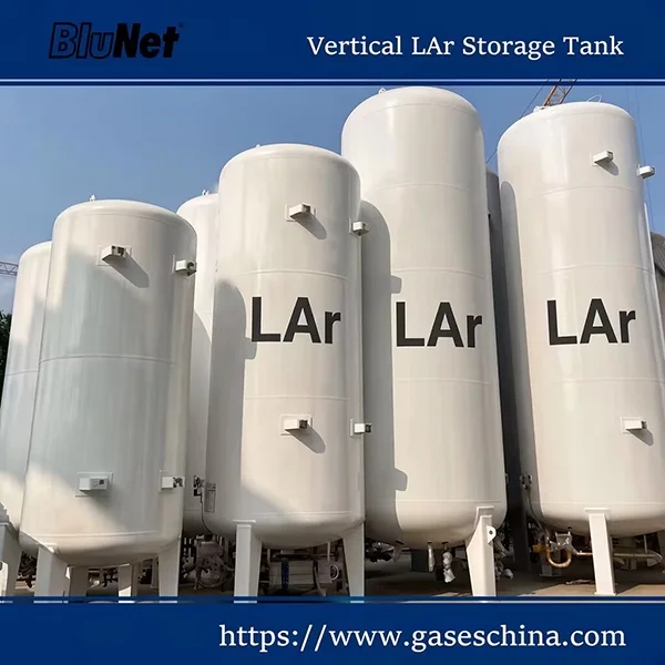
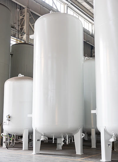
Vertical cryogenic tanks are commonly used for stationary bulk storage of liquid nitrogen (LN₂), liquid oxygen (LOX), liquid argon (LAR), and carbon dioxide (LCO₂). Their compact footprint makes them ideal for industrial plants, hospitals, laboratories, and manufacturing facilities where installation space is limited.
Key advantages include:
- Efficient use of site space
- Large storage capacities
- Excellent thermal performance
- Easy integration with vaporizers and gas supply systems
Horizontal Cryogenic Tanks
Horizontal cryogenic tanks are widely used where lower installation heights are required or where transportation and site access conditions favour horizontal configurations. They are commonly used for industrial gas storage, LNG fueling stations, and process plants.
Benefits include:
- Lower overall height
- Simplified transportation and installation
- Stable structural support
- Suitable for medium and large storage capacities
Microbulk Tanks
Microbulk tanks provide an efficient solution between gas cylinders and large bulk storage tanks. These vessels typically store liquid nitrogen, oxygen, argon, or carbon dioxide and are designed for users with moderate gas consumption requirements.
Typical applications include:
- Laser cutting
- Food processing
- Laboratories
- Healthcare facilities
- Metal fabrication
Microbulk systems reduce cylinder handling while providing a reliable and continuous gas supply.
ISO Tank Containers
Cryogenic ISO tank containers are designed for the international transportation of liquefied gases by road, rail, and sea. Built to ISO standards, these tanks provide safe and efficient intermodal transport of liquid nitrogen, oxygen, argon, LNG, and other cryogenic products.
Key features include:
- Global intermodal compatibility
- Vacuum-insulated double-wall construction
- High payload efficiency
- Compliance with international transport regulations
Cryogenic Semi-Trailers
Cryogenic semi-trailers are specialised transport vessels designed for bulk distribution of cryogenic liquids between production facilities and end users. These mobile storage systems offer large transport capacities while maintaining low boil-off rates during transit.
Commonly transported products include:
- Liquid nitrogen (LIN)
- Liquid oxygen (LOX)
- Liquid argon (LAR)
- Liquefied natural gas (LNG)
Flat Bottom LNG Tanks
Flat bottom LNG tanks are large-capacity LNG storage tanks used in LNG terminals, peak-shaving facilities, power plants, and liquefaction projects. These tanks are engineered to store significant volumes of liquefied natural gas safely and efficiently.
Typical features include:
- Very large storage capacities
- Double containment or full containment designs
- Advanced insulation systems
- Long-term LNG storage capability
Dewar Cylinders
Dewar cylinders are portable cryogenic vessels designed for the storage and transportation of smaller quantities of liquid gases. They are widely used in laboratories, medical facilities, biotechnology applications, and industrial operations requiring flexible cryogenic supply.
Advantages include:
- Portable and easy to handle
- Vacuum-insulated construction
- Suitable for liquid and gaseous withdrawal
- Available in various capacities
Each type of cryogenic storage vessel serves a specific role within the industrial gas supply chain, from small laboratory dewars to large-scale LNG storage tanks and international transport containers.
| Vessel Type | Typical Capacity | Typical Application |
|---|---|---|
| Dewar Cylinder | 30–500 L | Laboratory, Medical, Research Facilities |
| Microbulk Tank | 450–15,000 L | Small to Medium Gas Users |
| Vertical Cryogenic Tank | 3–200 m³ | Industrial Gas Storage |
| Horizontal Cryogenic Tank | 3–200 m³ | Industrial Gas Storage |
| ISO Tank Container | 10–50 m³ | International Intermodal Transport |
| Cryogenic Semi-Trailer | 20–60 m³ | Bulk Cryogenic Liquid Distribution |
| Flat Bottom LNG Tank | 1,000–200,000+ m³ | LNG Storage Terminals and Peak-Shaving Facilities |
Cryogenic Materials
Materials used in cryogenic vessel construction must retain strength and ductility at extremely low temperatures. Common materials include:
Stainless Steels
Austenitic stainless steels remain tough and ductile down to -269°C, making them ideal for cryogenic applications.
9% Nickel Steel
9% nickel steels combine austenitic and ferritic structures, offering excellent strength and resistance to brittle fracture. These materials are widely used for storing and transporting liquid gases like nitrogen, methane, and ethylene.
Aluminium Alloys
Alloys such as 5083 (Mg 0.445%, Mn 0.6%, Cr 0.15%) and 6003 (Mn 1.26%, Cu 0.12%) are commonly used for cryogenic vessels, air separation columns, and heat exchangers. They exhibit superior toughness and maintain structural integrity down to liquid helium temperatures (-269°C).
Copper Alloys
Copper alloys, including alpha brass and phosphorous-deoxidized copper, are still employed in small air separation plants. While their yield strength is lower than steel, their performance is reliable at cryogenic temperatures.
The following table compares the most commonly used materials in cryogenic vessel construction, highlighting their minimum service temperatures and typical industrial applications.
| Material | Minimum Service Temperature | Typical Cryogenic Applications |
|---|---|---|
| SS304 Stainless Steel | -196°C | Liquid Nitrogen (LN₂) Tanks, Cryogenic Piping, Dewars |
| SS316L Stainless Steel | -196°C | Medical Gas Storage, Pharmaceutical Systems, Food-Grade Applications |
| 9% Nickel Steel | -196°C | LNG Storage Tanks, Flat Bottom LNG Tanks, LNG Infrastructure |
| Aluminum Alloy 5083 | -269°C | Air Separation Units (ASU), Heat Exchangers, Cryogenic Columns |
| Invar Alloy | -269°C | Special Cryogenic Applications, Precision Low-Expansion Components, Aerospace Systems |
Thermal Insulation in Cryogenic Vessels
Thermal insulation is a critical component in cryogenic vessel design. Its primary function is to reduce heat ingress from the environment, minimising liquid gas evaporation (boil-off) and maintaining storage efficiency.
Key Insulation Methods
- Vacuum Insulation: A vacuum jacket between the inner vessel and outer shell dramatically reduces heat transfer by conduction and convection.
- Multilayer Insulation (MLI): Multiple layers of reflective foils separated by low-conductivity spacers reduce radiative heat transfer. Commonly used in large storage tanks and transport dewars.
- Foam or Perlite Insulation: High-performance foams or perlite fill provide thermal resistance in smaller tanks or where vacuum insulation is impractical.
Benefits of High-Quality Insulation
- Minimises boil-off, reducing loss of expensive cryogenic liquids.
- Maintains stable low temperatures for safe storage and transport.
- Improves energy efficiency and lowers operational costs.
- Enhances safety by preventing excessive pressure build-up due to evaporated gases.
Optimal insulation design considers vessel size, liquid type, ambient conditions, and storage duration. Combining vacuum insulation with multilayer reflective shields is the most effective solution for industrial applications.
How Cryogenic Storage Vessels Are Manufactured
The manufacturing of cryogenic storage vessels requires strict control of materials, fabrication processes, welding quality, and testing procedures to ensure safe operation at extremely low temperatures. Every stage of production must comply with applicable standards such as ASME, EN 13458, PED, or GB/T 18442.
1. Plate Preparation and CNC Cutting
Manufacturing begins with the inspection and preparation of certified raw materials. Stainless steel, 9% nickel steel, or aluminium alloy plates are cut to precise dimensions using CNC cutting equipment. Accurate cutting helps ensure proper fit-up, dimensional accuracy, and weld quality throughout fabrication.
2. Shell Rolling and Forming
The prepared plates are rolled into cylindrical sections using heavy-duty plate rolling machines. Heads and dished ends are formed according to the vessel design specifications. Dimensional checks are performed throughout the process to ensure compliance with engineering drawings and pressure vessel requirements.
3. Welding and Assembly
The inner vessel and outer shell are assembled using qualified welding procedures and certified welders. Common welding processes include:
- GTAW (Gas Tungsten Arc Welding) for root passes and precision welding applications.
- SAW (Submerged Arc Welding) for high-strength longitudinal and circumferential weld seams.
Strict welding controls help maintain structural integrity and pressure containment performance under cryogenic operating conditions.
4. Non-Destructive Testing (NDT)
All critical welds are inspected using non-destructive testing methods to verify weld quality and detect potential defects.
Common inspection methods include:
- RT (Radiographic Testing) for internal weld examination.
- UT (Ultrasonic Testing) for detecting subsurface discontinuities.
- PT (Liquid Penetrant Testing) for identifying surface cracks and imperfections.
NDT procedures are conducted in accordance with applicable design codes and customer specifications.
5. Vacuum Insulation and Vessel Evacuation
After assembly, the annular space between the inner vessel and outer shell is filled with insulation material such as perlite or multilayer insulation (MLI). High-vacuum systems are then used to evacuate the annular space, significantly reducing heat transfer and minimising liquid gas boil-off.
6. Pressure Testing and Leak Testing
Each cryogenic storage vessel undergoes pressure testing to verify structural strength and leak tightness. Depending on the design requirements, testing may include:
- Hydrostatic pressure testing
- Pneumatic pressure testing
- Helium leak testing
- Vacuum retention testing
These tests confirm the vessel’s ability to operate safely under specified pressure conditions.
7. Cold Shock Testing and Final Inspection
For selected applications, cold shock testing may be performed to evaluate material behaviour and structural performance under cryogenic temperatures. Final inspections verify dimensional accuracy, weld quality, insulation performance, safety devices, and compliance documentation before shipment.
Through rigorous manufacturing, inspection, and testing procedures, modern cryogenic storage vessels achieve the safety, reliability, and thermal performance required for industrial gas, LNG, medical gas, and cryogenic transportation applications worldwide.
The following table summarises the key manufacturing stages involved in cryogenic storage vessel production and their primary functions in ensuring safety, quality, and long-term cryogenic performance.
| Manufacturing Stage | Purpose |
|---|---|
| CNC Cutting | Material Preparation |
| Plate Rolling | Shell Forming |
| GTAW Welding | Precision Welding |
| SAW Welding | Structural Welding |
| RT / UT / PT Inspection | Quality Inspection and Weld Verification |
| Vacuuming | Thermal Insulation Performance and Heat Transfer Reduction |
| Pressure Testing | Structural Verification and Leak Tightness Validation |
| Cold Shock Testing | Cryogenic Performance Validation |
Need assistance selecting a cryogenic storage vessel?
Our engineering team can support you with complete technical and compliance solutions:
- Tank sizing and capacity selection
- Pressure and safety calculations
- Cryogenic system design optimization
- International standards and certification support
TECHNICAL FAQs
About The design of Cryogenic Vessel
Vessel thickness is designed according to ASME Section VIII Division 1, considering internal pressure, allowable stress at cryogenic temperatures, weld efficiency, and thermal stress conditions.
Heat ingress is minimized using high vacuum insulation (typically 10⁻³ to 10⁻⁶ mbar) combined with multilayer insulation (MLI) to reduce conduction, convection, and radiation heat transfer.
Common materials include austenitic stainless steel, 9% nickel steel, and aluminum alloys, all selected for their strength and toughness at extremely low temperatures.
A well-designed cryogenic storage vessel typically achieves a boil-off rate of less than 0.2% per day, depending on insulation performance and operating conditions.
Safety risks are controlled using pressure relief valves, rupture discs, and compliance with standards such as the ASME Boiler and Pressure Vessel Code.
Performance is verified through non-destructive testing (RT, UT, PT), vacuum integrity testing, and pressure testing in accordance with applicable international standards.

No comment